10 Industrial Robotics Integration Tips for Buyers
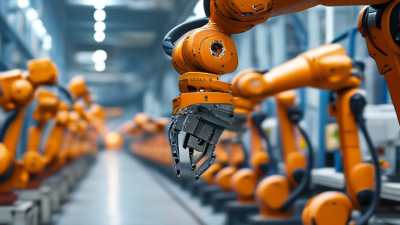
Industrial robotics integration is not simply a matter of buying a robot and placing it beside a production line. It connects equipment, people, software, safety procedures, and production goals into one working system. A six-axis arm may handle a repetitive pick-and-place task, yet its success depends on gripper choice, reach, cycle time, and consistent part delivery. Small details matter.
For buyers, early decisions shape a project’s cost and reliability. Confirm the process before selecting a robot. Document part dimensions, payload, required takt time, and expected changes in product mix. Review how the cell will fit around conveyors, operators, maintenance access, and existing controls. Ask integrators to explain their assumptions, test plans, and support arrangements in plain language. Request evidence from comparable applications, while checking whether the materials, cycle conditions, and uptime targets truly match yours. A polished demonstration is useful, but it is not a production guarantee.
Integration also involves trade-offs. A faster robot can create bottlenecks elsewhere, and extra sensors may add maintenance needs without solving the real constraint. Budget for commissioning, operator training, spare parts, and downtime—not hardware alone. Pilot runs can reveal awkward handoffs or unreliable part presentation before the full line is committed. Some estimates will change. That is normal, but unexplained changes deserve scrutiny. The ten tips ahead help buyers compare proposals, ask sharper questions, and plan a system that performs beyond the showroom.

Define the Use Case and Takt Time Against IFR’s 541,302 Robot Installations in 2023
In 2023, 541,302 industrial robots were installed worldwide, according to the International Federation of Robotics’ World Robotics 2024 report. It was the second-highest annual total recorded. That scale signals broad adoption, but it does not tell a buyer whether a robot suits a specific production line. Start with one defined task: for example, placing a 3-kilogram part into a fixture every 12 seconds. Record the required takt time, shifts, changeovers, and acceptable downtime. Vague targets make weak specifications.
Tip: Map the whole cycle, not just the robot’s motion. Include part arrival, gripping, safety checks, and handoff. Compare the measured cycle time with takt time, then leave capacity for small delays. A neat simulation can still miss a slow operator handoff or awkwardly placed bin.
Use real shift data where possible. Measure several production runs, including product changes and brief stoppages. Then ask integrators to explain assumptions behind cycle-time estimates and identify the bottleneck. These checks can feel tedious. They are. But a fast robot cannot fix inconsistent part supply, and adding speed may simply move the queue downstream. Revisit the target after a pilot; early estimates are often imperfect.
Match Robot Type to Application: Automotive Led 2023 Installations at About 25%
Automotive applications accounted for about 25% of industrial robot installations in 2023.
That share is significant. It is a useful signal, not a forecast for every factory; reporting methods and installation categories can differ. Buyers should match the robot to the task, not the headline. A vehicle-body welding cell, for example, needs reach, payload, and heat protection suited to its fixtures and cycle time. A compact assembly station may benefit more from a smaller robot with precise motion.
Map the actual work before comparing models.
Measure the heaviest part, tool weight, reach, and clearance around jigs, guards, and walkways. Check whether the robot can maintain the required cycle without awkward wrist angles. For repetitive pick-and-place, speed and repeatability may lead. For painting or welding, path consistency and process control matter more. The application sets the priorities.
Then test the layout with real parts and tools.
A digital simulation helps, but it may miss a cable snag or a fixture that blocks access. Small details matter. Ask integrators to document cycle assumptions, safety interfaces, and changeover time. Leave room for maintenance access. No plan is perfect; revisit it after a pilot run, when operators can point out what the drawings missed.
Size Cell Capacity Against IFR’s 4.28 Million Robots in Global Operation in 2023
IFR reported 4.28 million
industrial robots in operation worldwide in 2023. That scale shows automation is established, but it does not tell a buyer how large one cell should be. A global total is context, not a capacity target. Base your design on the parts, shifts, and output your site actually needs.
Start with required hourly production and the slowest reliable cycle time, not the robot’s advertised speed. Include loading, tool changes, inspection, and time for routine pauses. For example, a cell handling a part every 40 seconds may need a buffer if upstream delivery is uneven. Small buffers matter. Check payload with the gripper fitted, reach at every work position, and floor space for guarding and maintenance access. Then model demand across shifts and product changes. A cell sized for peak output can sit idle on ordinary days; one sized too tightly may miss targets after a short stoppage. The assumptions deserve a second look, especially if product mix or staffing changes often. Pilot the proposed cycle with real parts and operators before fixing the final capacity.
Assess Workforce Readiness Against the Global Density of 162 Robots per 10,000 Workers
A global density of 162 robots per 10,000 workers offers useful context, not a target every plant should copy. Industries, production volumes, and labor markets differ. Buyers should compare their own operation with relevant peers before estimating automation needs. A high robot count does not prove a workforce is ready.
Readiness shows up on the shop floor. Can operators safely clear routine faults? Are technicians available on every shift? Can process engineers adjust a cell when product dimensions change? Check maintenance logs, training records, and downtime by shift. Small gaps matter. A robot may stand idle because a gripper change takes hours, not minutes.
During supplier discussions, ask for a practical training plan and define who owns programming, recovery, and preventive maintenance. Run a pilot on one repeatable task, then record cycle time, stoppages, and support hours. Be honest about the weak spots. A spreadsheet can make staffing look adequate while the night shift has one qualified technician. That is easy to overlook. The 162-robot benchmark can frame the discussion, but local evidence should guide integration decisions.
Design Safeguarding to ISO 10218 and Collaborative-Robot Guidance in ISO/TS 15066
Industrial robot integration begins with the task, not the robot’s safety label. Map each operating mode, access route, and foreseeable fault before choosing safeguards. ISO 10218 provides safety requirements for industrial robots and their integration. In practice, inspect the whole cell: robot reach, gripper pinch points, conveyor openings, and nearby walkways. A fence may need interlocked gates, while light curtains or scanners may suit frequent access. Set protective distances using measured stopping performance, not guesswork. Labels are not enough.
Collaborative operation still requires a risk assessment. ISO/TS 15066 offers guidance for collaborative robot applications, including contact risks and force or pressure limits. A collaborative-rated robot alone does not make a cell safe. The tool, workpiece, speed, direction of contact, and surrounding fixtures all matter. A rounded tool can become hazardous when it carries a sharp part. Check whether the application uses hand guiding, monitored stops, speed-and-separation monitoring, or power-and-force limiting, and validate the chosen measures under real production conditions.
Document test results, stopping times, access checks, and changes to software or tooling. Train operators to recognize safe states and report unexpected motion. One weak point deserves extra attention: maintenance often bypasses normal production safeguards. Provide controlled procedures and verify them with the people who perform the work. Requirements can change with the installation and applicable standards editions, so have a qualified safety professional review the final design.